
Agnes
Email:saler3@kinscoter.com
Whatsapp:+86 16676870193
Mobile:+86 16676870193
Office: +86-768-2217942
WeChat: ik_THKJ1
After the exterior design is approved, a small appliance project moves from appearance definition into engineering development. The next goal is to integrate the internal structure, airflow path, electronics and agreed functions inside the approved product form.
In this article, an engineering sample refers to the Engineering Functional Prototype developed after appearance approval and before formal tooling. It is different from an appearance-only prototype and from a T0 sample made with formal injection molds.
For a direct comparison, read Appearance Prototype vs. Functional Prototype vs. T0 Sample.
The main exterior, dimensions, functions, controls and CMF direction have already been confirmed. The engineering team works from these approved inputs rather than restarting the product definition.
If a major requirement changes at this point, its effect on the structure, cost and schedule should be reviewed before engineering continues.
| Development Activity | What the Engineering Team Does | Main Output |
|---|---|---|
| Confirm engineering input | Check the approved appearance, functions and prototype scope | Defined engineering-sample scope |
| Plan component layout | Arrange the motor, battery, PCB, display, buttons and charging port | Preliminary internal layout |
| Develop the structure | Design supports, connections, fasteners, moving parts and assembly relationships | Internal mechanical 3D design |
| Integrate airflow and electronics | Coordinate the fan blade, motor, air inlet, air outlet, wiring and controls | Workable airflow and electronic direction |
| Produce prototype parts | Make rapid-prototyped housings and engineering parts | Components for prototype assembly |
| Assemble and debug | Build the sample and correct interference or functional problems | Testable engineering functional prototype |
| Review the sample | Record limitations and define corrections required before tooling | Engineering correction list |
These activities may overlap. Structural design, electronics, airflow and assembly often need to be adjusted together.
The first practical question is whether all required components can fit inside the approved exterior.
For a portable fan, the internal layout may include:
Motor and fan blade
Battery
PCB
Display
Buttons
Type-C charging port
Wiring
Internal supports
Safety-protection components
The engineering team checks whether the components have enough space, whether moving parts can operate without interference and whether visible controls align with the approved exterior. Product balance and assembly access are also considered.
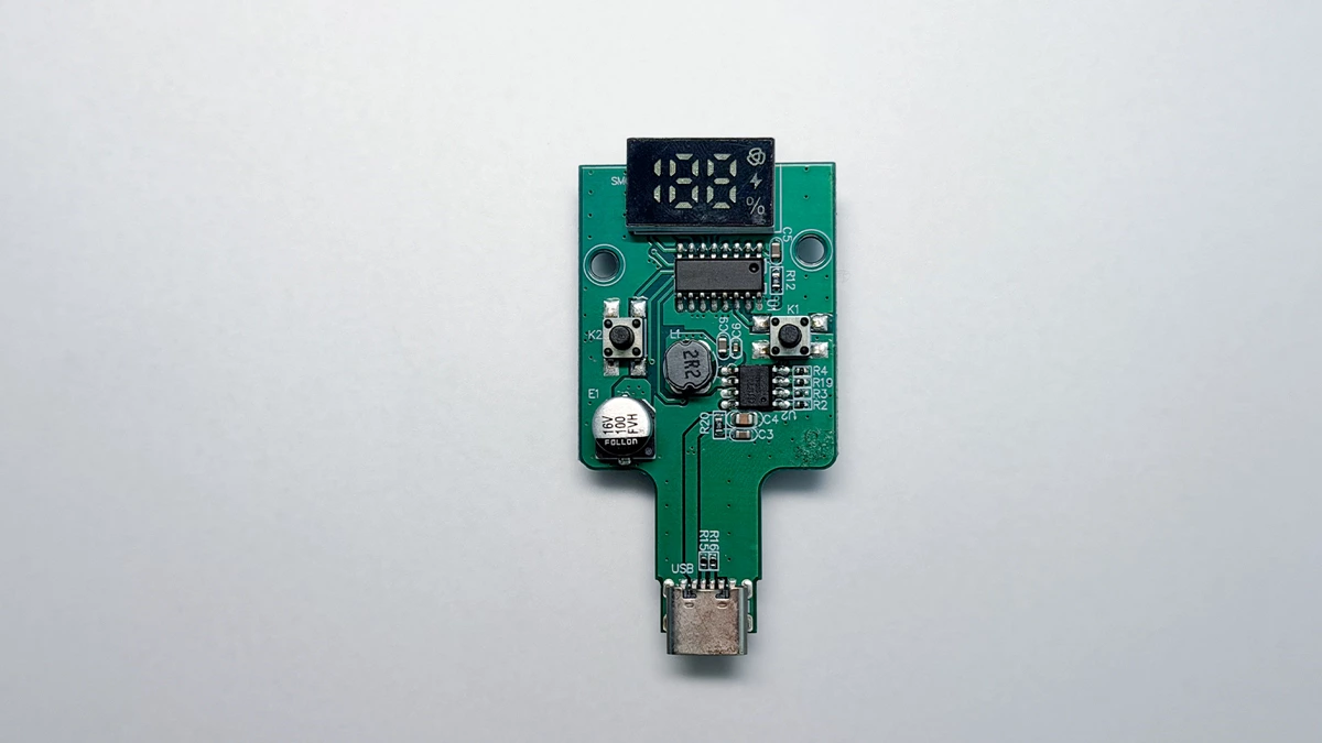
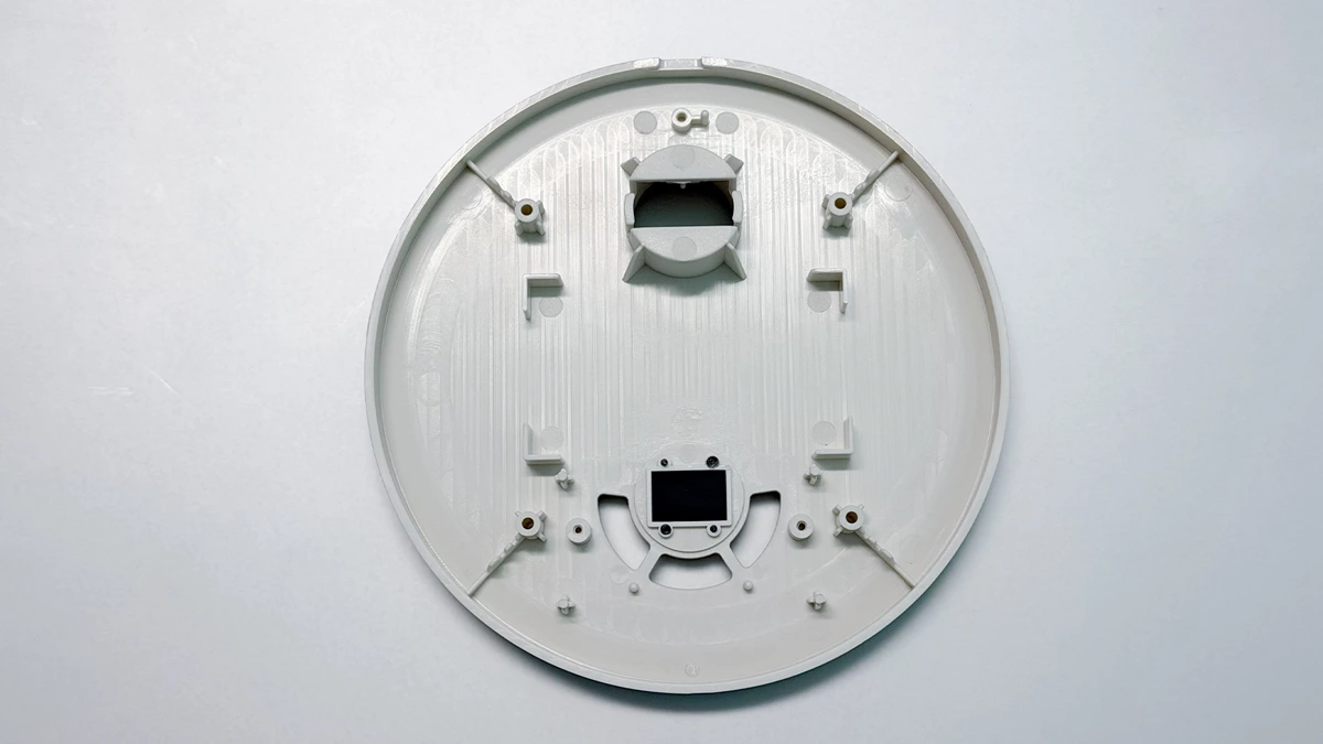
Suggested image: Portable fan internal structure design showing the motor, battery, PCB and housing layout.
A rendering shows how the product should look. Structural engineering determines how the product will be held together and how its functions will operate physically.
Depending on the fan type, this may include:
| Product Element | Structural Questions |
| Housing | How will the front and rear housings connect? |
| Motor | How will the motor be positioned and secured? |
| Battery | How will the battery be fixed and protected? |
| PCB and display | How will they align with the buttons and visible display area? |
| Front grille | Is it fixed or removable for cleaning? |
| Foldable joint | How will the joint rotate and hold its position? |
| Oscillation mechanism | Is there enough space for the motor and moving parts? |
| Clip or stand | Can it support the product securely in normal use? |
Screws, snap fits, locating features and assembly order are developed around these relationships. The parts must not only fit; they must also be practical to assemble.
For portable fans, the internal structure directly affects airflow, noise, power consumption and heat.
| Area | Engineering Consideration |
| Fan blade | Blade size and required rotation space |
| Motor | Mounting position, output direction and vibration control |
| Air inlet | Sufficient intake area without unnecessary blockage |
| Air outlet | Direction and effective delivery of airflow |
| Airflow path | Internal obstacles and clearances |
| PCB | Relationship with the motor, buttons, display and charging system |
| Battery | Size, location, fixation and charging solution |
| Heat | Space for heat generated by the motor, PCB or cooling module |
Industrial design defines the exterior direction. Engineering determines whether the airflow, electronics and components can work inside it. Any necessary visible change should be explained and approved.
After the engineering data reaches a workable stage, rapid-prototyped housings and structural parts are produced. The engineering team then installs the planned components and assembles the sample.
During assembly and debugging, the team checks:
Component fit and structural interference
Power, speed control, display and charging
Folding, oscillation or clipping mechanisms
Abnormal heat, noise, looseness or vibration
Assembly sequence and access
Problems found during assembly may require changes to the internal structure, component position, wiring or prototype parts.
Suggested image: Engineering functional prototype of a portable fan being assembled and tested before formal tooling.
An engineering sample is used to evaluate the proposed solution before the cost and lead time of formal tooling are committed.
| It Can Help Confirm | It Does Not Finally Confirm |
| Whether the main components fit | Final injection-molded surface quality |
| Basic structure and assembly relationships | Final production-material behavior |
| Agreed functions within the sample scope | Formal mold tolerances |
| Button and control logic | Mass-production consistency |
| Display and charging operation | Complete reliability life |
| Preliminary airflow and noise direction | Final certification results |
| Folding, oscillation or clip mechanisms | Final production approval |
Because the enclosure is normally made through rapid prototyping, its material behavior, surface finish and tolerances may differ from production parts. The sample confirms the engineering direction, not final production quality.
After appearance approval and confirmation of the engineering requirements, structural design and the Engineering Functional Prototype are normally completed in approximately 10–15 working days at Chaozhou Tongheng Technology Co., Ltd.
This period includes:
Component layout and mechanical 3D design
Airflow and electronic coordination
Rapid-prototype fabrication and assembly
Functional debugging and engineering correction
Internal sample review
The exact time depends on the product route and prototype scope. A modification based on a mature platform may reuse proven components and part of the internal structure. A completely new product normally requires more engineering development.
Buyer review time and major requirement changes are additional.
Buyers do not need to perform a full production inspection at this stage. They should focus on the items the engineering sample was created to demonstrate.
| Buyer Review Item | Main Question |
| Agreed functions | Do the functions included in the sample scope operate as expected? |
| Control logic | Are the buttons, speed settings, display and timer logic correct? |
| Handling | Is the product comfortable to hold, place, fold, clip or wear? |
| Basic performance | Is the airflow, noise and operating direction acceptable for this stage? |
| Exterior impact | Have engineering changes affected the approved appearance? |
| Known limitations | Does the buyer understand what cannot yet be confirmed? |
| Required corrections | Which issues must be corrected before tooling? |
Feedback should clearly separate required corrections from optional improvements. This helps the engineering team freeze the structure before tooling begins.
Formal tooling should begin only after:
The engineering functional prototype has been reviewed
Required corrections have been agreed
The function scope and control logic have been frozen
The final structural data has been updated
The tooling scope has been confirmed
Changing the battery, motor, PCB, display, controls, airflow path, overall dimensions or assembly method after tooling approval may require mold changes and additional lead time.
The buyer should therefore treat engineering-sample approval as an important investment gate rather than a routine sample confirmation.
No. Its enclosure and structural parts are normally made through rapid prototyping. Formal injection-molded parts first become available at the T0 mold trial stage.
Not necessarily. It tests the functions and engineering items defined for that prototype. Final production performance must still be verified using molded parts and the approved production configuration.
Minor changes may be required if the approved exterior creates an unavoidable conflict with the motor, battery, PCB, airflow path or assembly structure. Any visible change should be explained and approved before it is adopted.
They are closely connected, but the required corrections must first be incorporated into the final structure. Tooling should be authorized only after the updated engineering data and tooling scope are confirmed.
Engineering sample development connects an approved exterior design with a workable internal solution. It brings together the structure, airflow, electronics, controls and agreed functions before formal tooling begins.
For buyers, the purpose is simple: confirm that the proposed solution works, identify the remaining corrections and freeze the engineering direction before investing in production molds.
If you are planning a custom portable fan or another small appliance, contact Chaozhou Tongheng Technology Co., Ltd. to discuss the engineering scope, functional prototype and tooling plan for your project.
Tell us about your product or OEM/ODM requirements — our team will respond within one business day with product recommendations and manufacturing solutions.
Pick the specialist for your business — we reply within one business day.
Agnes
Email:saler3@kinscoter.com
Whatsapp:+86 16676870193
Mobile:+86 16676870193
Office: +86-768-2217942
WeChat: ik_THKJ1

Tina Chen
Email:sales2@cztongheng.com
Whatsapp:+86 152 1853 1931
Mobile:+86 152 1853 1931
Office: +86 768 221 7942
WeChat: czkinter

Charmy Zhou
Email:saler1@kinscoter.com
Whatsapp:+86 138 2832 9041
Mobile:+86 138 2832 9041
Office: +86 768 221 7942
WeChat: ik-THKJ